To supply the burners, two double-pump, automatically alternating pressure units are assembled. They are able to suction from either main tank, according to the gas oil level available in each of them. The main condition and precaution to be taken into account when designing the installation is preventing air from entering into the supply pipes and the burners for maintenance reasons or emptying of the line due to a fault. If this happens, purging all boilers would take a lot of work. For this reason, our goal is automatically isolating each burner in case of pressure drop.
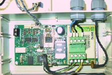
To ensure supply after all incidents, the second parallel pressure unit starts operation. Its suction pipe is independent, so if a unit is out of service, the second unit takes care of the entire flow. This operation is managed with the control panel.
Other condition to consider was controlling consumption in each burner with a gas oil meter, with the disadvantage of having to do the readings remotely, without creating a need of accessing each home for periodical consumption readings.
Solution adopted by INPRO
Pipe Line
Pipe recommendations are made according to the criteria of standard DIN 4755 indicating that gas oil speed in propulsion pipes must be between 1 and 1.5 m/s and in suction pipes between 0.2 and 0.5 m/s.
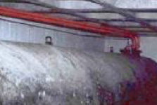
Main tank interstitial chamber detection
To detect leaks in the double skin of the main tank, we recommend a DDP-25 vacuum system with regenerative pump and fluid separation valve. The possibility of generating the vacuum again greatly decreases the incidence of false alarms and is compliant with standard EN 13160-1, Class 1.
Main tank control
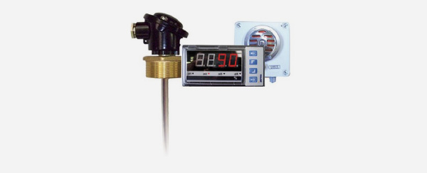
The available fuel level in each tank is controlled by digital displays EDM-40 with analog probes. The reading is displayed as an integer percentage, with a 4-20 mA output for communication with the central control of the airport technical building. The 90% and 20% relay outputs control the alarm systems to prevent overfilling when unloading the tanker and provide a reserve local signal
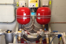
Pump Systems
Twin pressure units with two alternating motor pumps carry out the supply process.
These units are designed in such a manner that if any problem occurs in the motor pumps, an alarm signal will trigger and operation will automatically switch to the other pump, thus guaranteeing continuous pumping. Specifically, the GP-1500 GET with a 1500 L/h flow is selected. Each one has a collector tray with a spillage detection system by infrared sensors which sends a locking signal in case of spillage or leaking. The start-up and stop operation is conducted by the regulated pressure differential in the pressure switch, so the propulsion line is pressurized while the burner is turned off. When one of the burners is turned on, the pressure of the line decreases. When the level set as start-up is reached, the pumping process starts to recover the stop pressure. During each start-up, the pumps alternate automatically. The pressure switch has a third regulation point: minimum safety pressure. When reaching that point, usually 1 bar, the unit is blocked and sends a low pressure alarm signal. This prevents breaks or water tightness lost in the suction line and prevents no-load operation, along with a pressure transducer and a N.O. (normally open) solenoid valve in the propulsion pipe of each pressure group, which sends a signal to the control panel for it to manage their start-up and stop. Blocking the system in case of pressure drop and closing the solenoid valve.
The compact design of pressure units contains in one plate bench the other elements required for the operation of the unit. Expansion tank, filter with retention and safety valves, operation panel with thermal protection and vacumeter in suction and manometer in propulsion.
To comply with the pressure requirements at the inlet of the burners and knowing their consumption, adjustable pressure reducing valves are placed along with meters with a protective filter before them; the oil returns to the propulsion line with a retention valve. Moreover, an inverter pressure switch is placed at the inlet of each burner, set below the operating pressure. If pressure drops below this point, it sends a stop signal to the burner, preventing the propulsion pipe from emptying.
Consumption control
For measuring consumption in each home, a volume meter is installed at each point of use with an output signal linked to a radio frequency emitter, programmed to periodically send a data packet with the weekly consumption log. A data concentrator is installed in the technical building of the facility, linked to a computer with the software required to receive and manage the individual consumption data individually and thus erasing the need of accessing the homes. The system has anti-fraud alarms that trigger if there are inconsistencies in the readings.
IMAGES OF THE PROJECTS
Elements of the installation supplied by INPRO
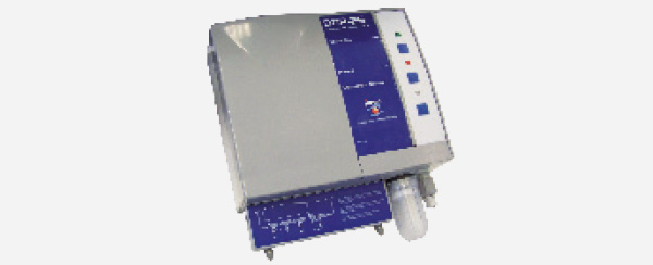
PROBE EDM40
Continuous level display and control unit completely adapted to the needs of the installation. Displays the level at all times, expressed as a percentage. All required operations can be done via the relay module and the analog communication output. Customized manufacture makes this unit perfect for all kinds of tanks and a wide array of fluids.
- Standard operating temperature: 40ºC that can be adapted to reach up to 125ºC.
- Control unit in standardized module (DIN 43700) 96 x 43 x 100, can be mounted with panels.
- Flexible probe with sealed head, can be fastened with 2’’, 11/2’’ or 1’’ nuts. Mounted with aluminum or standardized flange..
- Overfilling warning alarm triggering with 95 dB acoustic signal, automatic shut-off and reset push button with IP-55 protection. It complies with the requirements of the standard MI-IP03 on “Oil Installations for own consumption”.
INTERSTITIAL CHAMBER DETECTOR DDP-25
Vacuum leak detector for interstitial chamber in double-skinned tanks according to EN 13160-1, Class 1.
- Has a regenerative pump controlled with an adjustable vacustat. Thus keeping a -400 mBar pressure between the inner and outer skins of the double-skinned tank. When dropping below 380 mBar, the pump regenerates the vacuum; if there are any holes, the negative pressure does not regenerate; the alarm triggers upon reaching 340 mBar.
- These units are perfect for tanks of up to 3 m of diameter.
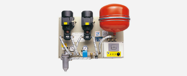
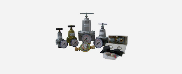
PRESSURE UNIT GP GET
Gas oil pressure unit for automatic supply to burners and pumping to emergency generators via pressure adjustment. Start-up and stop operations via an adjusted pressure switch, which allows planning the installation without control wiring.
- Gear electric pumps with three-phase or single-phase supply.
- Motor protection IP-55
- System to interrupt no-load operation in case of lack of fuel
- Alternative electronic control management system
- Vacumeter
- Aluminum filter, retention valves and safety valve with exhaust line
- Possibility of digital outputs for incident control from central control with 3, 4 or 6 signals. GSM alarm system via SMS messages or modem connection
- Adaptation of the Units for high pressure, operating conditions up to 8 Kg/cm2.
- Modifications for adapting tropicalized and ATEX units
- Assembly process in sound-proof sheet cabinets with UNE-25 poly-pyramid foam and lock. Manufactured with no back and IP-55 cabinets for outdoors installation.
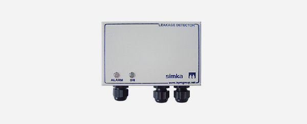
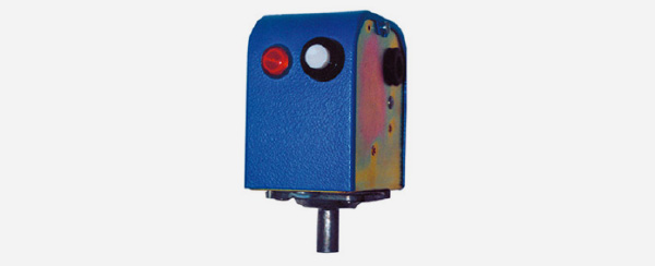
COLLECTOR TRAY WITH SPILLAGE DETECTOR
Placing collector trays under certain elements of the installation is recommended. Particularly, equipment that could leak due to its characteristics or during maintenance tasks. Placing a spillage detector for the tray gives the possibility of creating protocols.
- Furnace-painted plate tray with the appropriate size for each circumstance.
- Spillage detector in the control panel and detection probe. Infrared optical sensor for oil and water, conductivity sensor for water or both, mounted on the same probe.
- Standard 1.5 m probe.
- The control unit of the detector is mounted in a box with impact-resistant plastic cover. The control unit contains two voltage free relays, one for commuting and the other one usually open.
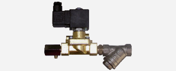
SOLENOID VALVES
Set of solenoid valves to control the filling process and safety against spillage due to excessive levels.
- Chrome plated brass Y-shaped filter, with stainless steel 0.05 mm mesh PN16.
- Gas oil N.C. solenoid valve to control the filling process.
- A regulated and sealed container (flow limiter) adapted to the desired flow, consisting of a chrome plated brass valve and nylon seals.
- Gas oil N.O. solenoid valve to control the filling process.
PRESSURE REDUCING VALVE
Adjust the propulsion pressure to the burner or pump line operating needs.
- Output pressure adjustable with manometer or fixed, depending on the model.
- Flow between 20 and 3,000 L.
PRESSURE SWITCH
Adjustable pressure switch for start-up in pressure unit according to the defined adjustment. Independent operation and safety micro switches.
- Connection by 10 mm crimp fitting for compression coupling.
- Adjustable operation pressure between 1.5 and 6.5 bar
- Adjustable safety pressure between 0.5 and 2 bar
METER
Meters for gas oil, fuel, kerosene, gasoline and lubricants
- Flow meter for hydrocarbons and co-generation in burners, ships, vehicles and fixed facilities.
- Metrological certificates and calibrations available based on regulatory needs.
- The whole model range provides the best solutions to measure fuel consumption
- State-of-the-art designs in electronic meters, with analog and digital outputs with parametrizable values.
- Propulsion or suction assembly.
- Independent from viscosity and temperature
- System monitoring and control simplifies the configuration of the burner and the optimization of consumption
- Maximum safety in shipbuilding and automotive industry