PALMA DE MALLORCA AIRPORT
Supply to power generator units with pressure unit
The customer requested gas oil pumping to the daily service tanks of the emergency or normal operation power generator units. This could be done in several ways; in each case, we would assess the redundancy and safety needs and requirements in order to provide the method with a higher warranty of complying with the needs of the installation concerned, without forgetting any details that could simplify and reduce the costs of the assembly and future maintenance tasks.
In this case, pumping to both circuits would be done via two twin pressure units with two alternating motor pumps. Both circuits are designed in such a manner that if one of them stops working, the fuel can be redirected manually with manual shut-off valves. The pumping flow of each pressure unit is calculated so a single unit can provide the total flow of the system.
Solution adopted by INPRO
Pipe Line
Pipes were selected according to the criteria of standard DIN 4755 indicating that gas oil speed in propulsion pipes must be between 1 and 1.5 m/s and in suction pipes between 0.2 and 0.5m/s.
Main tank interstitial chamber detection
Leak detection in the double skin of the main tanks is done with a DDP-25 vacuum system with re-generator pump and fluid separation valve. This greatly decreases the incidence of false alarms and is compliant with standard EN 13160-1, Class 1. Installation in daily service tanks is not recommended, as they do not have double skin.
Control of main tanks
EDM-40 continuous level measurement digital displays with analog output (0-10V – 4/20 mA) are installed for local reading of the tank capacity, as well as a 95 dB alarm to prevent overfilling during the unloading process of the tanker.
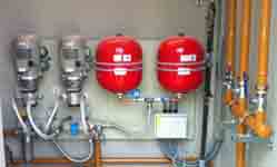
Pump Systems
A twin pressure unit is mounted on each circuit with two alternating motor pumps. Specifically, we selected GP-800 GET with a flow of 800 L/h. These units are designed in such a manner that if any problem occurs in the motor pumps, an alarm signal will trigger and operation will automatically switch to the other pump, thus guaranteeing continuous pumping. Each one has a collector tray with a spillage detection system by infrared sensors which sends a locking signal in case of spillage or leaking. The start-up and stop operation is carried out via the regulated pressure differential in the pressure switch, so the propulsion line is pressurized while the N.C. operation valve is closed. When one of the tanks drops below the minimum level set in the probe, the N.C. solenoid valve opens, which decreases the pressure of the line and the pumping process starts until recovering stop pressure. During each start-up the pumps alternate automatically. The pressure switch has a third regulation point: minimum safety pressure. When reaching that point, usually 1 bar, the unit is blocked and sends a low pressure alarm signal. This prevents breaks or water tightness loss in the suction line and prevents no-load operation of the pump. The compact design of pressure units contains in one plate bench the other elements required for the operation of the unit. Expansion tank, filter with retention and safety valves, operation panel with thermal protection and vacumeter in suction and manometer in propulsion. The possible pressure drop in the propulsion line is controlled via inverter pressure switches installed at the outlet of the pressure unit.
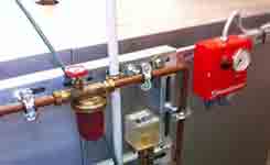
Daily service tank filling
Daily service tanks will be filled with a control and safety system consisting of: Filter, N.C. (normally closed) solenoid valve for filling control, N.O. (normally open) solenoid valve for maximum level safety and a flow limiter. The solenoid valves are managed by a control panel consisting of a touch screen panel automaton on the front of the operation panel with the analog and digital signals corresponding to tank control and status via level probes, overfilling safety flow switch in the vents and spillage protection systems.
Operation is conducted via a level differential in the daily service tank. When the level drops down to 70%, the level switch issues an opening order to the N.C. solenoid valve, the line pressure drops down to the start-up point of the pumping unit and start-up and stop operations are performed until reaching 90%; a closing order is then issued to the N.C. valve. The unit remains in standby after reaching the maximum operating pressure.
If due to a failure of the N.C. valve or the pressure unit operation the level exceeds 90%, there is a high level safety milestone at 95% that launches the return pump to the main tank, until reaching 75%.
All operation and safety protocols are managed by the automaton, as well as communication with the airport central control with Mod-bus.
IMAGES OF THE PROJECTS
Elements of the installation supplied by INPRO
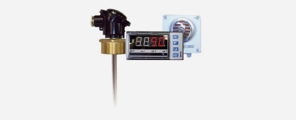
PROBE EDM40
Continuous level display and control unit completely adapted to the needs of the installation. Displays the level at all times, expressed as a percentage. All required operations can be done via the relay module and the analog communication output. Customized manufacture makes this unit perfect for all kinds of tanks and a wide array of fluids.
- Standard operating temperature: 40ºC that can be adapted to reach up to 125ºC.
- Control unit in standardized module (DIN 43700) 96 x 43 x 100, can be mounted with panels.
- Flexible probe with sealed head, can be fastened with 2’’, 11/2’’ or 1’’ nuts. Mounted with aluminum or standardized flange..
- Overfilling warning alarm triggering with 95 dB acoustic signal, automatic shut-off and reset push button with IP-55 protection. It complies with the requirements of the standard MI-IP03 on “Oil Installations for own consumption”.
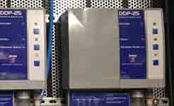
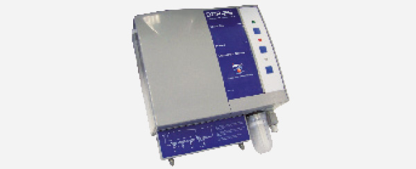
INTERSTITIAL CHAMBER DETECTOR DDP-25
Vacuum leak detector for interstitial chamber in double-skinned tanks according to EN 13160-1, Class 1.
- Has a regenerative pump controlled with an adjustable vacustat. Thus keeping a -400 mBar pressure between the inner and outer skins of the double-skinned tank. When dropping below 380 mBar, the pump regenerates the vacuum; if there are any holes, the negative pressure does not regenerate; the alarm triggers upon reaching 340 mBar.
- These units are perfect for tanks of up to 3 m of diameter.
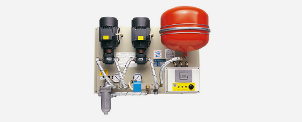
PRESSURE UNIT GP GET
Gas oil pressure unit for automatic supply to burners and pumping to emergency generators via pressure adjustment. Start-up and stop operations via an adjusted pressure switch, which allows planning the installation without control wiring.
- Gear electric pumps with three-phase or single-phase supply.
- Motor protection IP-55
- System to interrupt no-load operation in case of lack of fuel
- Alternative electronic control management system
- Vacumeter
- Aluminum filter, retention valves and safety valve with exhaust line
- Possibility of digital outputs for incident control from central control with 3, 4 or 6 signals. GSM alarm system via SMS messages or modem connection
- Adaptation of the Units for high pressure, operating conditions up to 8 Kg/cm2.
- Modifications for adapting tropicalized and ATEX units
- Assembly process in sound-proof sheet cabinets with UNE-25 poly-pyramid foam and lock. Manufactured with no back and IP-55 cabinets for outdoors installation.
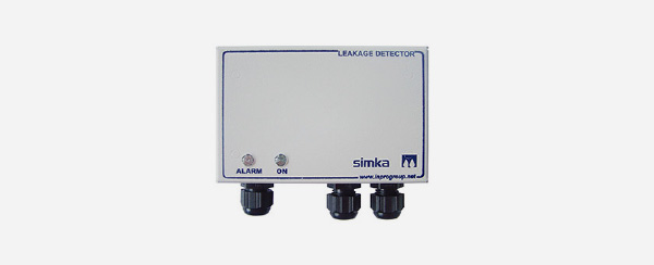
COLLECTOR TRAY WITH SPILLAGE DETECTOR
Placing collector trays under certain elements of the installation is recommended. Particularly, equipment that could leak due to its characteristics or during maintenance tasks. Placing a spillage detector for the tray gives the possibility of creating protocols.
- Furnace-painted plate tray with the appropriate size for each circumstance.
- Spillage detector in the control panel and detection probe. Infrared optical sensor for oil and water, conductivity sensor for water or both, mounted on the same probe.
- Standard 1.5 m probe.
- The control unit of the detector is mounted in a box with impact-resistant plastic cover. The control unit contains two voltage free relays, one for commuting and the other one usually open.
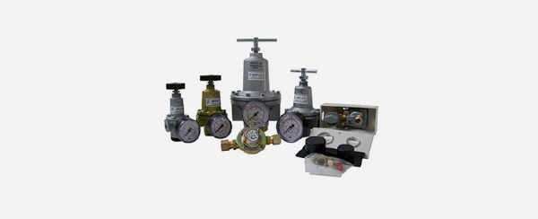
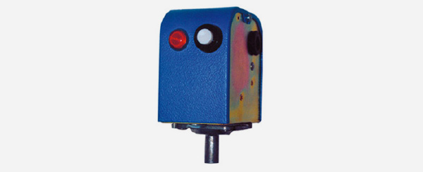
PRESSURE SWITCH
Adjustable pressure switch for start-up in pressure unit according to the defined adjustment. Independent operation and safety micro switches.
- Connection by 10 mm crimp fitting for compression coupling.
- Adjustable operation pressure between 1.5 and 6.5 bar
- Adjustable safety pressure between 0.5 and 2 bar
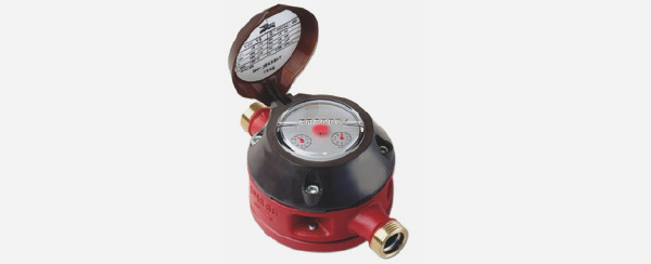
METER
Meters for gas oil, fuel, kerosene, gasoline and lubricants
- Flow meter for hydrocarbons and co-generation in burners, ships, vehicles and fixed facilities.
- Metrological certificates and calibrations available based on regulatory needs.
- The whole model range provides the best solutions to measure fuel consumption
- State-of-the-art designs in electronic meters, with analog and digital outputs with parametrizable values.
- Propulsion or suction assembly.
- Independent from viscosity and temperature
- System monitoring and control simplifies the configuration of the burner and the optimization of consumption
- Maximum safety in shipbuilding and automotive industry
PRESSURE REDUCING VALVE
Adjust the propulsion pressure to the burner or pump line operating needs.
- Output pressure adjustable with manometer or fixed, depending on the model.
- Flow between 20 and 3,000 L.