05. GP-GC
OIL TRANSFER PRESSURE UNITS- HIGH FLOW SYSTEMS- From 2,000 l/h to 12,000l/h
1 pump- 2 pumps
Inpro pressure units are equipment used to transfer liquid fuel such as diesel or HVO from a main tank to different consumption points through the pressurization of a line, for the supply of machinery that requires these fuels, such as generators (power generators) or burners for boilers in buildings..
There are several sizes and configurations of equipment, in which the flow rate that can control the equipment can vary (from 30l/h to 12,000 l/h), the maximum pressure at which they can work, with the possibility of redundancy in some components, and other parameters such as the type of power supply..
It can be Normal or Twin equipment that duplicates critical components to increase reliability.- Gas threaded flange DIN-2576 PN-1
- For high flow rates from 2,200 l/h to 12,000 l/h.
- Perfect for critical facilities such as airports, hospitals or Data Centers.
- 2 pumps skid possibility that duplicates critical components to increase reliability.
- Includes an infrared leak detection system.
- 6 signals output for reporting status and alarms to central BMS
Application area example
Small units (from 30l/h to 1,500l/h) can be used for:- The supply of boilers in single-family houses.
- Community of neighbors buildings
- Small installations.
- Large buildings requiring 24h/7 electricity
- Data Centers
- Hospitals
- Airports
- Malls...
Applications & Specific Features
- Multiple burner, appliances or service tanks supplied with one GP pressure unit.
- Appliances installed at different heights.
- Modulating burners when using the Inpro Oil Burner Inlet Assembly (see Datasheet).
- Oil Supply installation using ‘dead leg’ pipework. GP unit does not need external controls.
- GP units operate on an internal pressure switch only pumping fuel when required.
- Pressure regulators may be required at oil inlet to burners/appliances.
- Limited suction lift may require GP unit to be sited near the oil tank.
Accessories and Adaptations
- Free voltage relay output to control from centralised Building Management System, in kit 3, 4 or 6 signals (2-thermal, motors 1 or 2 ON, low pressure and Leak safety ON).
- GSM alarm system by SMS messages, or connection to modem.
- Adaptation of Pressure Group for high pressure, working conditions of up to 6 Kg/cm2
- Leak collector trays with infrared detectors (standard in GP-800 and GP-1500).
- Modifications to adapt to specifically regulated environments with tropicalised equipment or ATEX.
- Solenoid valve
Technical Features
| MODEL | GP-2200 NT GP-2200 GE | GP-3200 NT GP-3200 GE | GP-4200 NT GP-4200 GE | GP-6500 NT GP-6500 GE | GP-8500 NT GP-8500 GE | GP-12000 NT GP-12000 GE | |
|---|---|---|---|---|---|---|---|
| FLOW | l/h | 2200 | 3200 | 4200 | 6500 | 8500 | 12000 |
| CONNECTION TO THE HYDRAULIC CIRCUIT (Ø THREAD / Ø mm) | SUCTION | 1” F | 1” 1/2 F | 1” 1/2 F | 2” F | 2” F | 2” F |
| DRIVE | 3/4” F | 1” F | 1” 1/4 F | 1” 1/2 F | 1” 1/2 F | 2” F | |
| POWER SUPPLY | VOLTS | 230/400 tri-phase | 230/400 tri-phase | 230/400 tri-phase | 230/400 tri-phase | 230/400 tri-phase | 230/400 tri-phase |
| MOTOR POWER | C.V. | 2 | 2 | 3 | 4 | 4 | 5,5 |
| KW | 1,5 | 1,5 | 2,2 | 3 | 3 | 4 | |
| MAX. PRESSURE | kg/cm2 | 3,5 | 3,5 | 3,5 | 3,5 | 4 | 4 |
| SAFETY VALVE OPENS AT: | kg/cm2 | 4,5 | 4,5 | 4,5 | 4,5 | 4,5 | 4,5 |
| PIPPING SUCT/PRES | 1½” / 1” | 2” / 1¼” | 2½” / 1½” | 2½” / 1½” | 3” / 2” | 3” / 2½” | |
| MOTOR PROTECTION | IP | 55 | 55 | 55 | 55 | 55 | 55 |
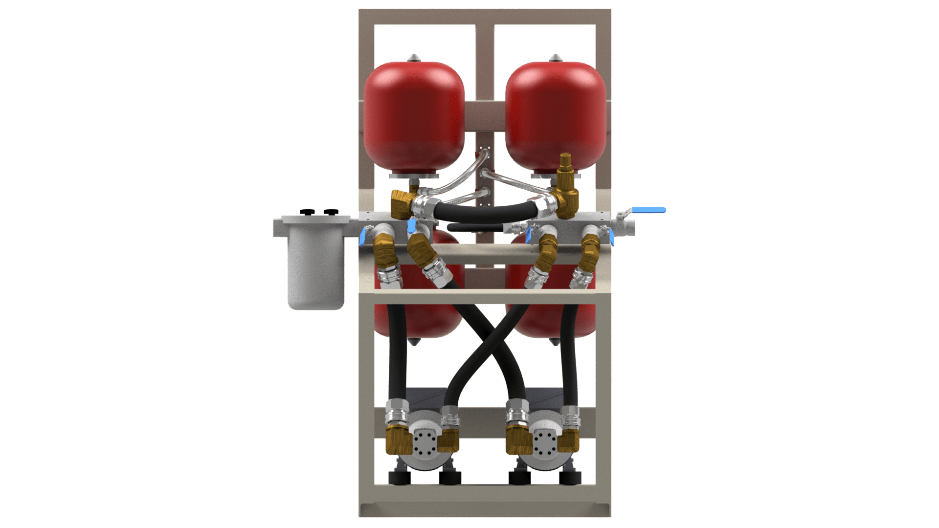
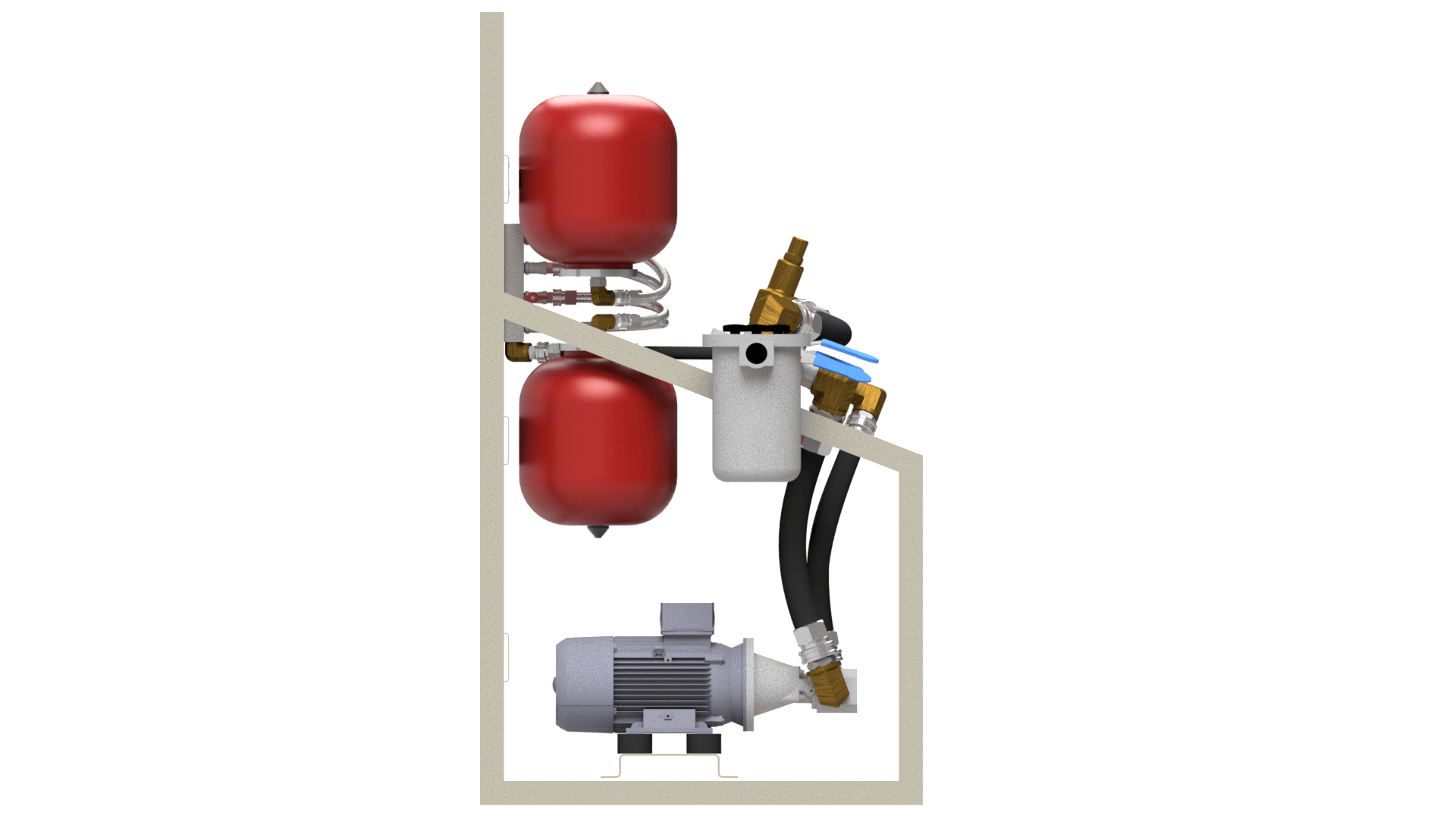
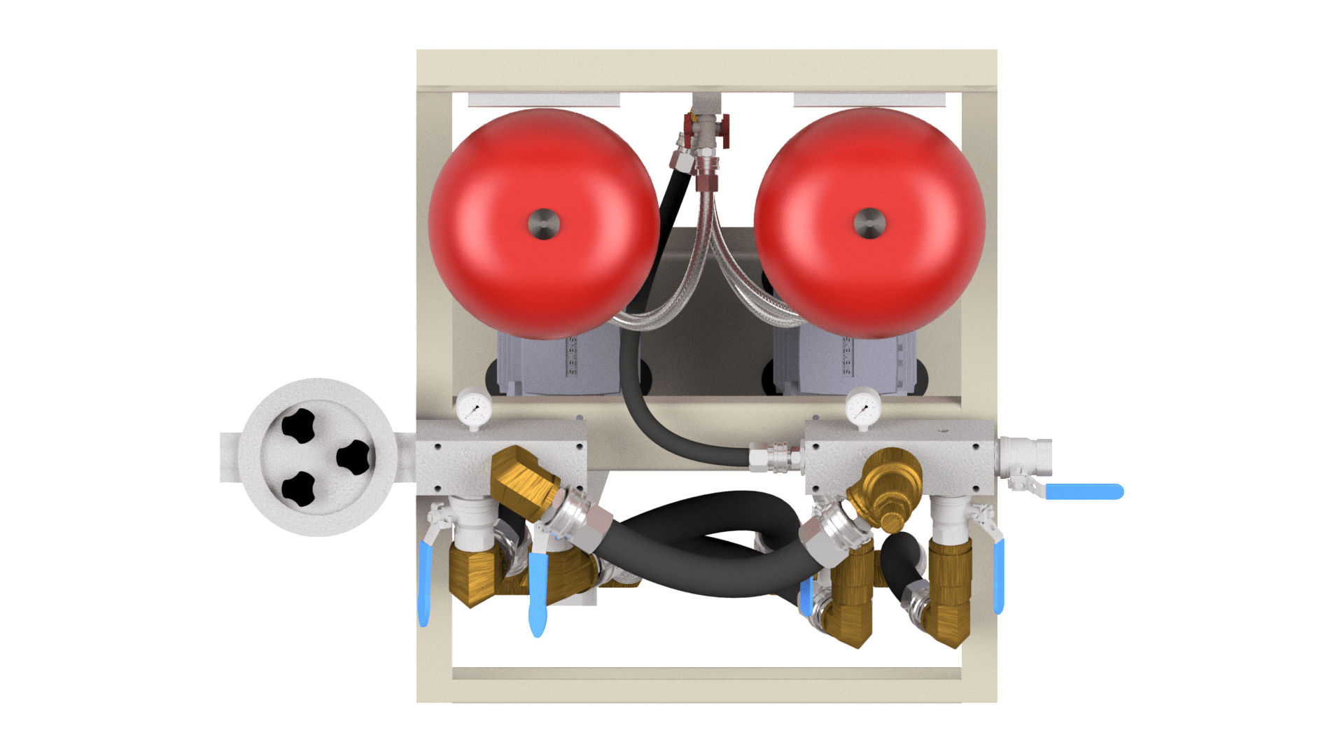
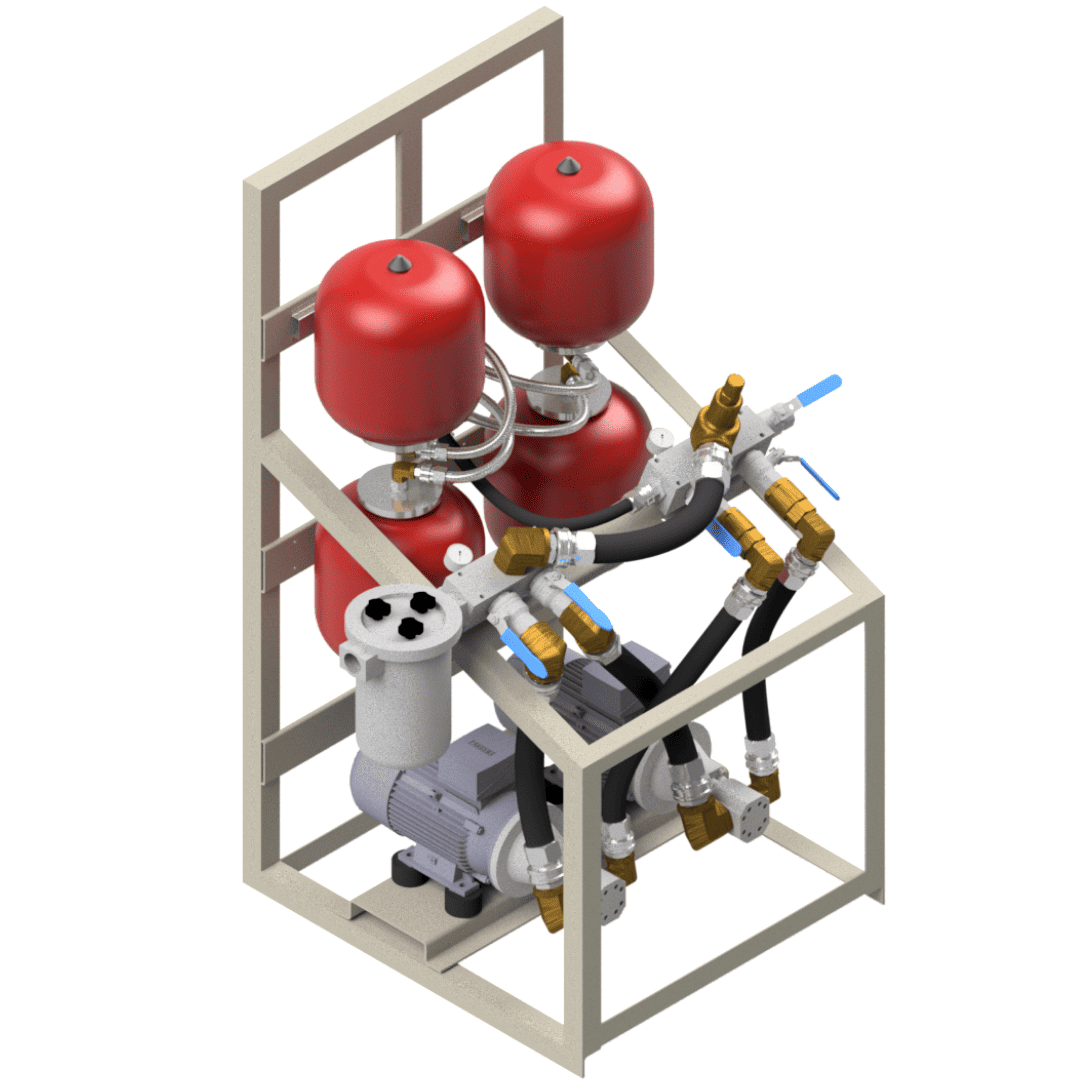
3D Pictures
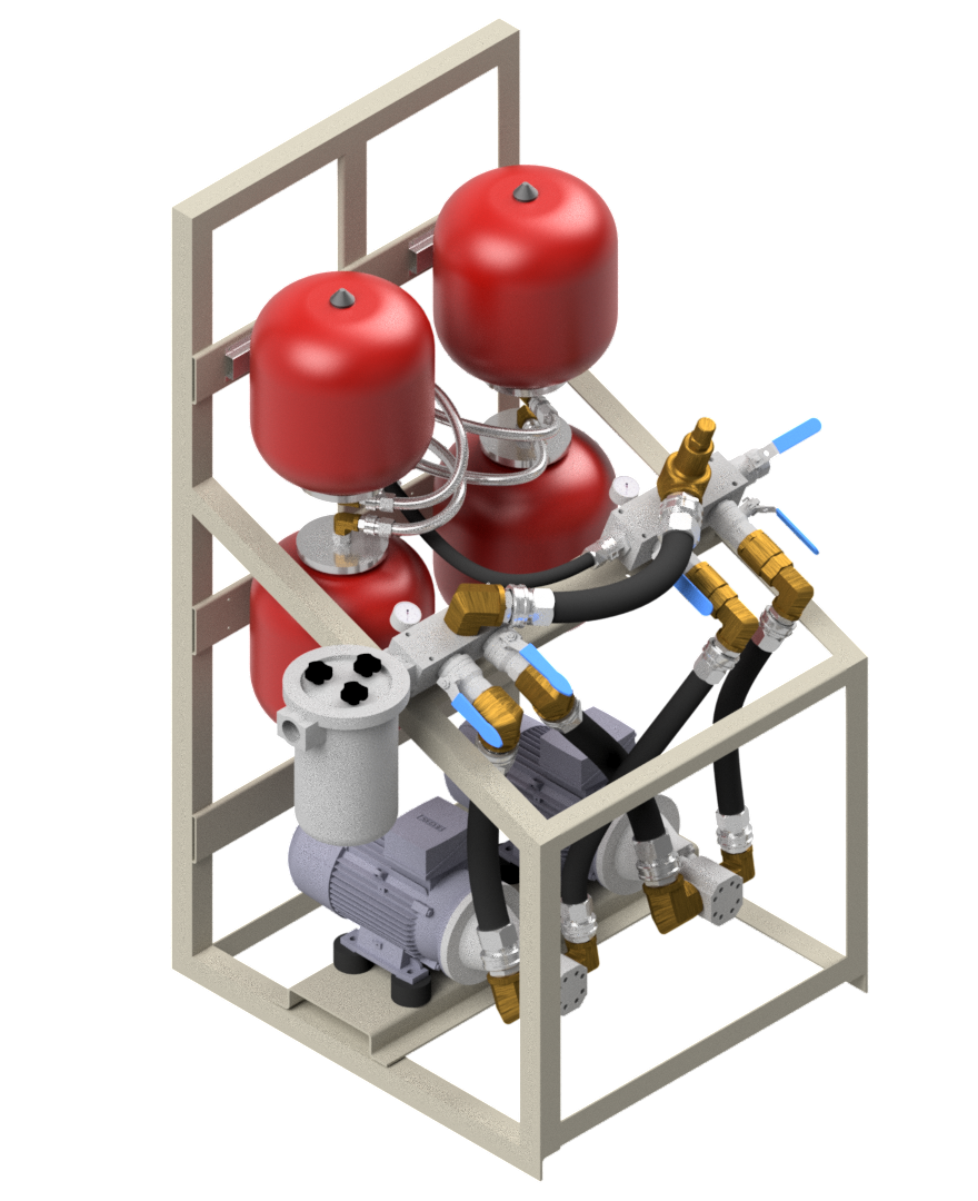
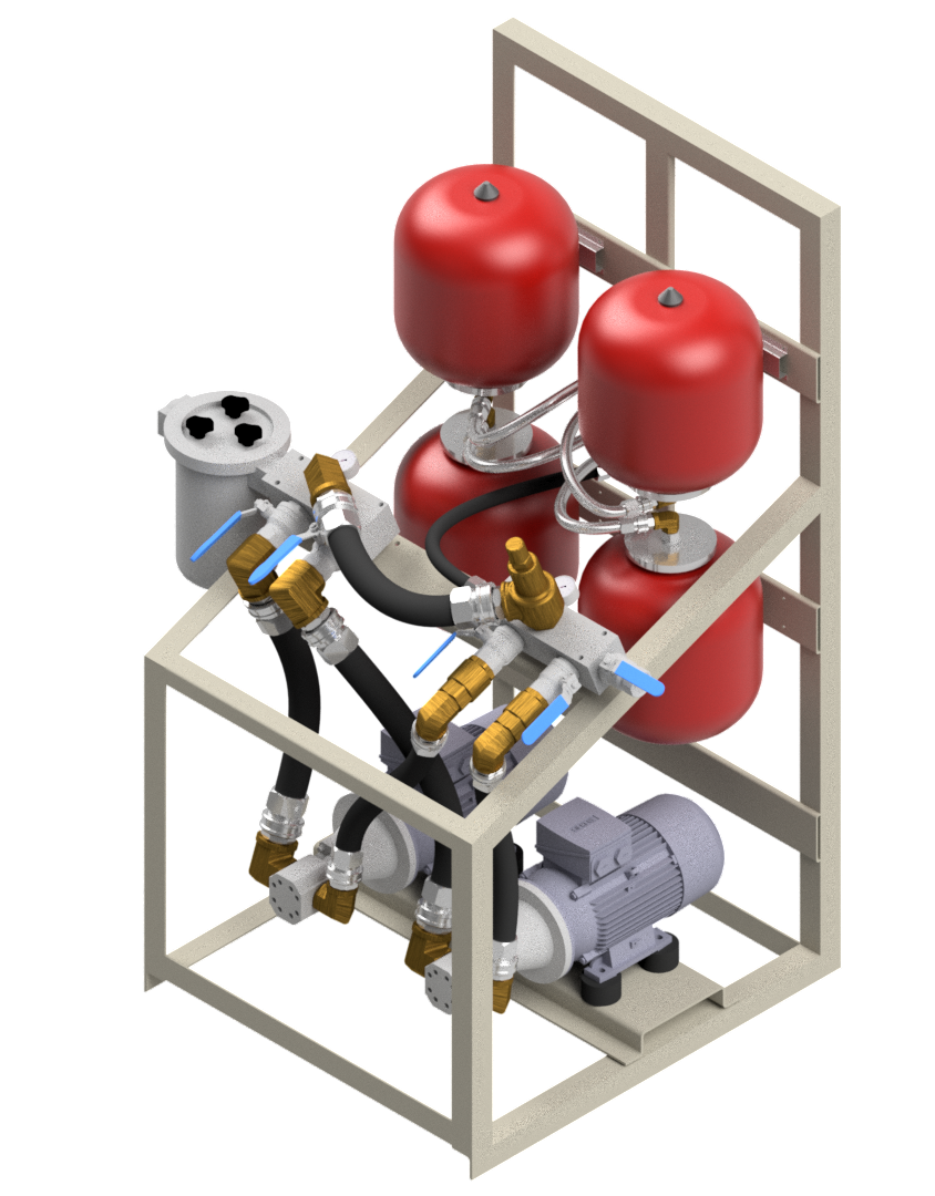
3D Vídeo Animation
Images